
- #Negedge detector verilog code full
- #Negedge detector verilog code code
- #Negedge detector verilog code license
I don't think this will work as-is, but it should give you a bit of an idea. For eight bits, shift the MSB of data_reg into spi_data, and shift the rest up one bit. The other option would be to use a separate counter register. This is a simple way to use the state register as a counter. states 1-8 are captured by the default: block. When write_enable is asserted, save datain to datareg and proceed to transmit states (1-8). input wire reset input datain input clk input write_enable output reg spi_data reg state = 0 reg datareg always clk) begin if (reset) begin state <= 0 spi_data <= 0 end else case (state) 0: if (write_enable) begin datareg <= datain state <= 1'b1 end 9: begin spi_data <= 0 state <= 0 end default: begin spi_data <= datareg datareg <= datareg state <= state + 1'b1 endcase end This does: - After reset, go to the idle state (0). You should use write enables and busy flags to control how the module works with other parts of the system. Write_en <= 1'b1 // to ensure shifting is done only once.Unless you're doing combinatorial logic, always blocks should only be triggered by clocks, and occasionally an asynchronous reset if you have a good reason to use one.
#Negedge detector verilog code code
Read_en <= 1'b1 // to ensure correct read operation end else if(!mode_strobe & !bus_rw & !write_en) // condition for indicating FPGA the end of one row begin if(bus_in = 8'b0110_0110) // '66' is code indicating end of row begin for(index=0 index < 34 index = index + 1) // this loop will implement row shift operation begin RAddr <= RAddr + 1 // incrementing to next RAddr location. We include RTL code and simulation environments, so that users can simulate the rendering. code is written from 1.ġ: bus_out <= out1 // this block will implement a 32:1 8 bit Vectored MUX Then the basic Verilog syntax is explained with basic examples.
#Negedge detector verilog code license
Plate License Recognition in Verilog HDL 9. Verilog code for Fixed-Point Matrix Multiplication 8.

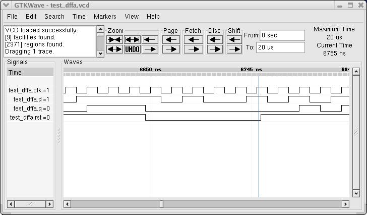
Verilog code for 32-bit Unsigned Divider 7. Verilog code for basic logic components in digital circuits 6. Programmable Digital Delay Timer in Verilog HDL 5. Write_en <= 1'b1 // this ensures correct write operation end else if(!data_strobe & bus_rw & !read_en) // condition for reading from FPGA begin case (RAddr+1) // initially RAddr is 0. Verilog code for 16-bit single-cycle MIPS processor 4. WAddr <= WAddr + 1 // setting write pointer to next location Row3 <= bus_in // writes the data at bus_in to RAM location pointed by WAddr Write_en <= 1'b0 // this enables writing to FPGA for(index=0 index<34 index=index+1) // to avoid the don't care values.įor(index=0 index<34 index=index+1) // -do-īus_out <= 8'hff // to set bus_out reg value to FF end else if(!data_strobe & !bus_rw & !write_en) // condition for writing data to FPGA begin Read_en <= 1'b0 // this enables reading from FPGA RAddr <= 6'b0 // this sets read address to initial location WAddr <= 6'b0 // this sets Write Address to initial position reg index // used as variable in shifting operation assign bus = (bus_rw)? bus_out : 8'dz // this code enables the duplexing of 'bus' assign bus_in = (!bus_rw) ? bus : 8'dz // -do- // codes till ' always' is for instantiating 32 sobels wire out1 input clk // CLOCK! reg row3 // 34 byte RAM reg row2 // 34 byte RAM reg row1 // 34 byte RAM reg WAddr // 6 bits to move upto 34th location reg RAddr // 6 bits to read 32 sobel outputs and future developments reg write_en,read_en // internal registers for correct read/write operations. Please also see the waveform attached to the original post. Rule 2: Whenever a rising edge is seen, if another rising edge was also seen no more than 15 clock cycles previously, then the output goes low. Pin1 READ=1 WRITE = 0 input reset // No other special meanings. Rule 1: Whenever a falling edge is seen, the output goes high. input mode_strobe // The Mode Strobe signal on pin 17 (address strobe) // is used to indicate the setting of the mode in fpga, Modes yet to be decided (TODO) input bus_rw // Indicates the direction of data on the data_bus.

input data_strobe // The Data Strobe signal on pin 14 of the parallel port. Inout bus // 'bus' is a bi-directional bus reg bus_out // 8 bit internal register for storing output values wire bus_in // this is used to get input data when 'bus' is acting as input. */ module imageedge(bus,data_strobe, mode_strobe, bus_rw,clk, reset) * The complete verilog code that interfaces parallel port and calls sobel core modules.
#Negedge detector verilog code full
The following is the full verilog code for the project.


 0 kommentar(er)
